


جميع المنتجات
-
 رود آلان، فرنسامن الجيد جدًا العمل مع محترفين حقيقيين. إنهم منتبهون ومتجاوبون.
 -
 أليخاندرو جيدي، المكسيكتواصل ممتاز من البائع. كانت السيدة ديزي واضحة وفي الموعد المحدد، وتم شحن المنتج مع تغليف مناسب. A+
 -
 سيرجي شابوتكين، الاتحاد الروسيكل شيء على ما يرام
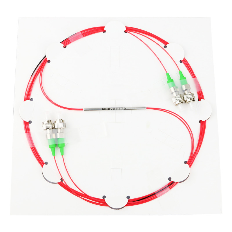
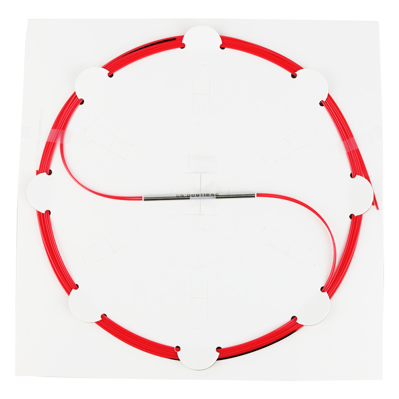
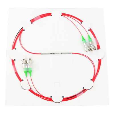
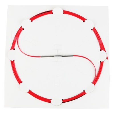
1550nm 2x2 Polarization-Maintaining (PM) Fiber Optic Splitters/Couplers/Taps


تفاصيل المنتج
| تكوين المنفذ | 2 × 2 | طول الموجة المركزي | 1550nm |
|---|---|---|---|
| النطاق الترددي | ±15 نانومتر أو ±40 نانومتر | الخسارة الزائدة | 0.3 ديسيبل (النوع)، 0.4 ديسيبل (الحد الأقصى) |
| نسبة الانقراض | 20 ديسيبل (الحد الأدنى) | خسارة العودة | 55 ديسيبل (الحد الأدنى) |
| الاتجاهية | 50 ديسيبل (الحد الأدنى) | الأعلى. مستوى الطاقة | 500 ميجاوات (مع الموصلات أو الألياف العارية) 2 وات (مقسمة) |
| نوع الألياف | ألياف PM Panda | محاذاة محور الاستقطاب | كلا المحورين يعملان |
| حجم الحزمة | Ø3.0 مم × 54.0 مم | سترة | أنبوب فضفاض من Hytrel® بقطر 900 ميكرومتر |
| تحميل الشد ضفيرة | 5N | نطاق درجة حرارة التشغيل | -40 إلى 85 درجة مئوية |
منتوج وصف
Fiber Optic Splitters/Couplers/Taps
1550nm 2x2 Polarization-Maintaining (PM)
Description
These 2x2 Polarization-Maintaining (PM) Fiber Couplers are designed for operation at 1550 nm and are available with a 50:50, 60:40, 70:30, 75:25, 80:20, 90:10, or 99:1 coupling ratio. 2x2 couplers are bidirectional and can be used to both split and combine signals.
PM couplers are manufactured using PANDA fiber, which allows them to maintain a high polarization extinction ratio (PER) when light is launched along the slow axis of the fiber. As seen in the diagram below, stress rods run parallel to the fiber's core and apply stress that creates birefringence in the fiber's core, allowing polarization-maintaining operation. Typical applications for PM couplers include optical sensors, optical amplifiers, and fiber gyroscopes.
Our High Polarization Extinction Ratio (PER) Couplers provide a PER of ≥25 dB when measured with connectors while the standard PM Couplers provide a PER of ≥20 dB when measured with connectors. All the couplers have a specified operating temperature range of -40 °C to 85 °C but the actual PER will vary slightly over the entire range. Note that within an optical system the achievable PER is always limited by the element with the lowest PER within the system.
All of these 1550 nm couplers have a maximum power handling of 1 W with connectors or bare fiber and a maximum power handling of 5 W when spliced. These couplers undergo extensive individual testing and verification of the PER.
Couplers are available with 2.0 mm narrow key FC/PC and FC/APC connectors. When using the couplers as a combiner, connect a fiber terminator to the unused output port, as a fraction of the light will travel through this leg of the device. Fiber leads are jacketed in Ø900 µm Hytrel®* tubing and the leads are 0.8 m long. Custom coupler configurations with other wavelengths, fiber types, coupling ratios, alignment axes, or port configurations are also available. Please contact us with inquiries.
*Hytrel® is a registered trademark of DuPont Polymers, Inc.
PANDA PM Fiber Cross Section
![]()
The connector key is aligned to the slow axis of the fiber.
Features
* 1550 nm Polarization-Maintaining Fiber Optic Couplers
* 50:50, 60:40, 70:30, 75:25, 80:20, 90:10, or 99:1 coupling ratio
* Bidirectional Coupling (Either End Can Be Used as an Input)
* 2.0 mm Narrow Key FC/PC or FC/APC Connectors
* 0.8 m Long Fiber Leads with a Tolerance of +0.075 m / -0.0 m
* ≥20.0 dB or ≥25.0 dB Polarization Extinction Ratio (PER) Options
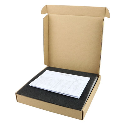
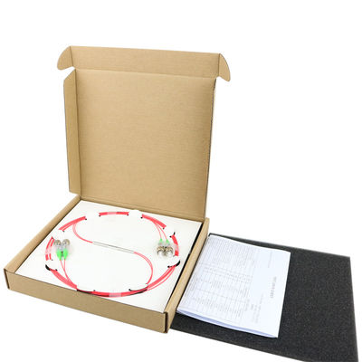
* Individual Test Report Included with Each Coupler
* Contact Us for Custom Wavelength, Coupling Ratio, and Connector Options
Specifications
| Item | Specification |
| Port Configuration | 2x2 |
| Center Wavelength | 1550nm |
| Bandwidth 1 | ±15nm or ±40nm |
| Excess Loss 1 | 0.3dB (Typ.), 0.4dB (Max.) |
| Extinction Ratio 2 | 20dB (Min.) |
| Return Loss 1 | 55dB (Min.) |
| Directivity | 50dB (Min.) |
| Max. Power Level 3 |
500 mW (With Connectors or Bare Fiber) 2 W (Spliced) |
| Fiber Type 4 | PM Panda Fiber |
| Axis Alignment | Both Axis Working |
| Package Size | Ø3.0 mm x 54.0 mm |
| Jacket | Ø900 µm Hytrel® Loose Tube |
| Pigtail Tensile Load | 5N |
| Operating Temperature Range | -40 to 85 °C |
| Storage Temperature Range | -40 to 85 °C |
| Coupling Ratio 1 | Coupling Ratio Tolerance | Coupling Ratio 1 | Coupling Ratio Tolerance |
| 50:50 | ±4.8% | 5:95 | ±1.5% |
| 40:60 | ±3.9% | 3:97 | ±0.8% |
| 30:70 | ±2.5% | 2:98 | ±0.7% |
| 20:80 | ±2.3% | 1:99 | ±0.5% |
| 10:90 | ±2.1% | 0.5:99.5 | ±0.2% |
Notes:
1. Values are specified with a slow axis launch at room temperature without connectors and measured at the center wavelength through the input port.
2. Specified with a slow axis launch at room temperature with connectors and measured at the center wavelength through the input port.
3. Specifies the total maximum power allowed through the component. Coupler performance and reliability under high-power conditions must be determined within the user's setup. See Usage Tips for safety and handling information.
4. The fiber used in this coupler is compatible with patch cables using Coherent’ PM1550-XP fiber, Other fiber types may be available upon request. Please contact us with inquiries.
Usage Tips
1. Before connecting a component to a system, make sure the light source is turned off. Inspect both the input and output fiber ends; debris or contamination on the end face can lead to fiber damage when operated at high power.
2. After connecting the component, the system should be tested and aligned using a light source at low power. The system power can be ramped up slowly to the desired output power while periodically verifying all components are properly aligned and that coupling efficiency is not changing with respect to optical launch power.
3. Optical connectors can be removed and the device can be spliced into a setup for operation at higher optical powers. Fiber ends should always be cleaned and cleaved prior to splicing.
Ordering Information
Port Configuration,
Wavelength,
Coupling Ratio,
Package Type, Fiber Type,
Input: Connector Type, Cable Diameter, Cable Length
Output: Connector Type, Cable Diameter, Cable Length
Other Special Requests
Example:
Polarization-Maintaining Fiber Coupler,
2x2,
1550nm,
50:50,
Tube type, Corning Panda PM 1550 fiber,
Port 1: FC/APC, 0.9mm, 1.5 Meters,
Port 2: FC/APC, 0.9mm, 1 Meter,
Port 3: FC/APC, 0.9mm, 1.5 Meters,
Port 4: FC/APC, 0.9mm, 1 Meter.
*0.9mm Color-coded Tube
*Note: Customized Color-coded Combination is Available.
المنتجات الموصى بها