


جميع المنتجات
-
 رود آلان، فرنسامن الجيد جدًا العمل مع محترفين حقيقيين. إنهم منتبهون ومتجاوبون.
 -
 أليخاندرو جيدي، المكسيكتواصل ممتاز من البائع. كانت السيدة ديزي واضحة وفي الموعد المحدد، وتم شحن المنتج مع تغليف مناسب. A+
 -
 سيرجي شابوتكين، الاتحاد الروسيكل شيء على ما يرام
Optimize PM Fiber Alignment for Different Applications with PER Testers


تفاصيل المنتج
| نطاق القياس | 0-100 ٪ | تقليل فقدان الإدراج | <2.0 ديسيبل |
|---|---|---|---|
| أطوال موجية معايرة | 1310/1490/1550/1625 نانومتر | مصدر الطاقة | بطارية |
| درجة حرارة التخزين | -10-50 درجة مئوية | نموذج الألياف | 9/125um سم |
| مادة | بلاستيك | وزن | 50g |
| درجة حرارة التشغيل | 0-40 درجة مئوية | الطول الموجي | 1260 ~ 1650nm |
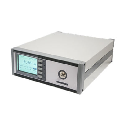
| نوع العرض | شاشات الكريستال السائل | موصل بصري | FC/PC |
منتوج وصف
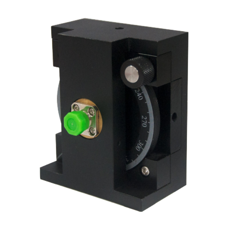
Extinction Ratio Tester
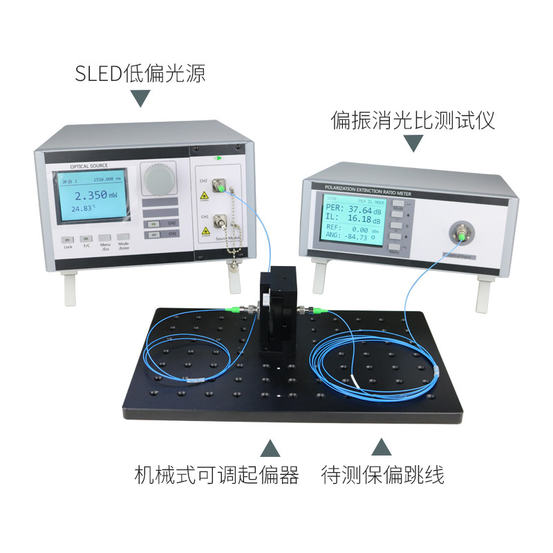
The benchtop unit uses the rotating polarizer method to quickly and accurately measure the polarization extinction ratio (PER) of polarization-maintaining (PM) fibers, which makes it easy to optimize the alignment of PM fibers for different applications, such as making PM pigtails for laser diodes, improving the coupling efficiency of linearly-polarized light to PM fibers, making splices for PM fibers and fusion splicing of PM fibers.
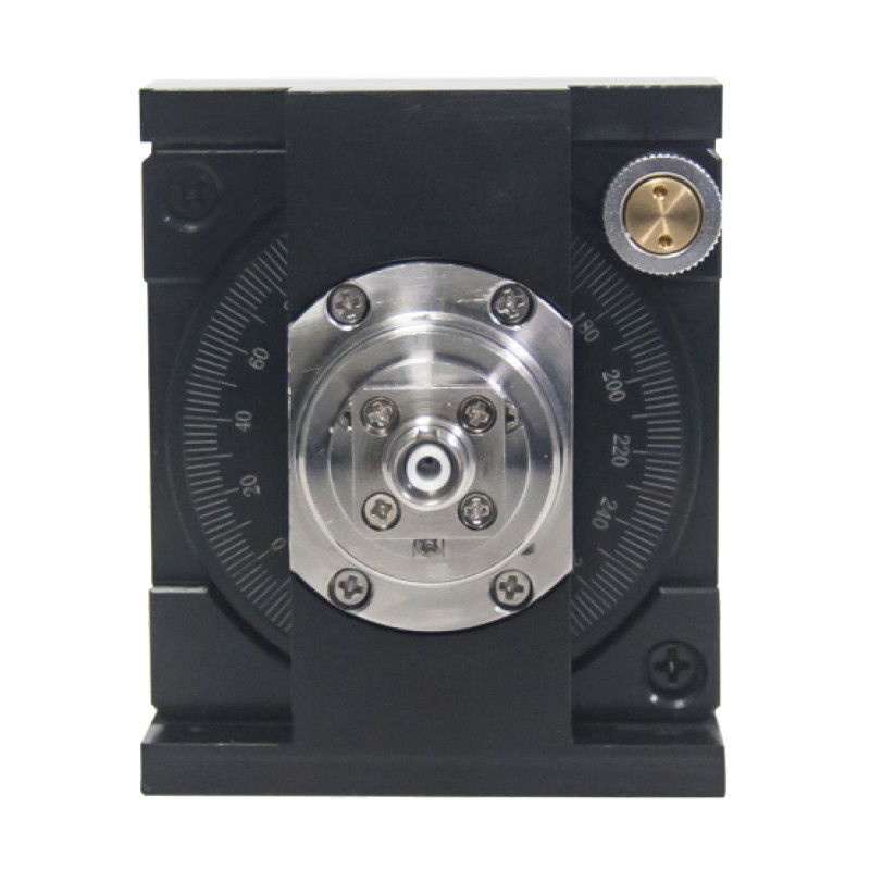
SLD and ASE broadband light sources are more suitable for use as light sources for aligning PM fibers. They generally emit light of unknown polarization, so a polarizer is added in front of the fiber input to generate line-polarized light; it is recommended that the transmission axis of the polarizer be perpendicular to the base plate. If the splice key is aligned with the slow axis of the PM fiber and the splice key is in the vertical direction, then the light is coupled in the slow axis of the PM fiber.
Feature:
High extinction ratio
Low insertion loss
High stability and reliability
Low insertion loss
High stability and reliability
Application:
Fiber Laser
Fiber Amplifier
Fiber Optic Sensing
Fiber Optic Communication
Instrumentation
Fiber Amplifier
Fiber Optic Sensing
Fiber Optic Communication
Instrumentation
Application 1: Fabrication of PM pigtails for laser diodes The coherent nature of the laser light has to be taken into account here, as it can lead to erroneous components in the PER results. Therefore, in addition to optimizing the current extinction ratio, the effect of pseudo-polarized light needs to be reduced by applying stresses as a means of determining a conservative value of ERmin as well as the optimal direction of rotation of the PM fiber.
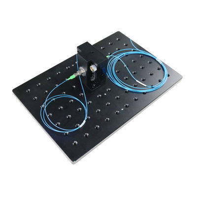
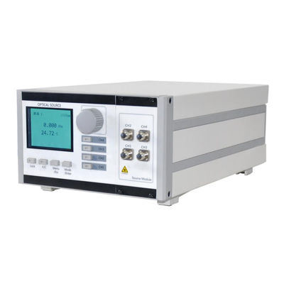
Application 2: Aligning Line Polarized Light and PM Fiber Patch Cords The use of an SLD or ASE light source is recommended here, and the alignment procedure is as follows: 1. Insert the output connector of the PM fiber into the extinction ratio tester's fiber adapter, and then turn on the unit. 2. Connect the input of the FiberBench to an SLD light source, and the input connector of the PM fiber to the output of the FiberBench. 3. The FiberBench is equipped with a polarizer, but the coupling optics depend on the light source, so they are not listed here.3. Display the actual ER value in ER mode.4. Rotate the fiber until the maximum ER value is displayed. Application 2: Aligning Line Polarized Light and PM Fiber Patch Cords It is recommended to use an SLD or ASE light source for this application. The alignment procedure is as follows: 1. Insert the output connector of the PM fiber into the fiber adapter of the extinction ratio tester, and turn on the unit. 2. Connect the input of the FiberBench to the SLD light source, and connect the input connector of the PM fiber to the output of the FiberBench. 3. The FiberBench is equipped with a polarizer, but the coupling optics depend on the light source, so they are not listed here.3. Display the actual ER value in ER mode.4. Rotate the fiber until the maximum ER value is displayed.
المنتجات الموصى بها